Product code: N/A
5SHY4045L0006 High-Voltage Excitation System
📣Model Number:5SHY4045L0006
🌍Country of origin: USA France Germany Estonia Norway UK
⌚Delivery date: in stock
🛠After-sales service: brand new with one year warranty
⚙️ Product Category: Module/Controller/Server/Motor/Touch Screen
🕰Warranty: 12 months/365 days
☎️ Please contact me: 15359029662 Ms. Amy Sun
📎Chinese official website: www.dcsplcabb.com
📩Email: geabbamy@gmail.com
💬Whatsapp: +86 15359029662
Detailed content
5SHY4045L0006
The key to success was in the GTO itself. More precisely, the only thing wrong with it was an enormous control problem. Because of the demand for high turn-off amplification, the GTO passes through a region during the transition from the conducting (thyristor) to the non-conducting (transistor) states when both anode voltage and cathode current are impressed (red background). As with a mechanical switch, however, a four-layer device can only assume one of two stable states — on and off. The transition tends to instability and has to be got through as quickly as possible and be supported by snubber
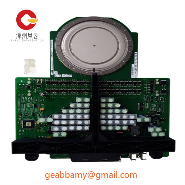
The rate-of-change of the drive is critical for the operation of the GCT. The cathode current has to be turned off in less than 1 µs, otherwise the device moves into the unstable part of the characteristic. This corresponds to dIG/dt ≥ 3000 A/µs for a 3 kA GCT and proportionally more or less for other types. The voltage needed results for a given inductance of the gate circuit, respectively the inductance for a given gate voltage.
On the other hand, a simple, reliable and cost-effective drive unit is only possible at low voltages. An ideal voltage is –20 V, because the gate can withstand this voltage after turn-off. The permissible leakage inductance for interrupting 3 kA is 6 nH or less which is only 1/50 of the usual value for a GTO. It was possible to achieve this value by adopting a coaxial configuration of the device connection and a multi-layer connection to the power output of the drive


